8086 microprocessor | what is 8086 microprocessor | Introduction of 8086 microprocessor | Features of 8086 microprocessor | Pin Diagram of 8086 microprocessor |
-: 8086 Microprocessor :-
8086 microprocessor is the first 16 bit microprocessor that was designed by Intel in 1978 using HMOS technology. 8086 microprocessor is advanced version of 8085 microprocessor. It has 20 bit address was so it can directly access 1 MB memory location. It consists of powerful instruction set which provides operations like multiplication and division easily.
8086 microprocessor support to type of mode operation that is minimum mode and maximum mode operation
Features of 8086 microprocessor:- 8086 microprocessor is 16 bit microprocessor. The arithmetic logic unit internal register and most of its instruction are designed to work with 16 bit binary word.
8086 microprocessor has 20 bit address bus and 16 bit data bus.
8086 has multiplexed address and data bus which reduce the number of pins.
8086 require 1 face clock with 33% duty cycle.
It has a instruction queue which is capable to storing six instruction byte from the memory resulting in faster processing.
8086 microprocessor used pipeline to fetching and execute the improve performance.
8086 microprocessor has segmented memory.
The operation of 8086 microprocessor is faster than 8085 microprocessor.
It uses a 5V DC supply to operate
Pin diagram of 8086 microprocessor
8086 microprocessor is the first 16 bit microprocessor designed by enter in 1978 using h much technology. It is available in 40 pin DIP chip. It uses 5V DC supply to operate it has 20 bit address bus and 16 bit data bus and the address was operate in multiplex mode. 8086 is the advanced version of 8085 microprocessor.
Pins of 8086 microprocessor can be classified into following groups shown in figure.
1-AD15-AD0(multiplex bus)-There are 16 bit address / data bus or multiplexed bus. AD0-AD7 carries Lo order byte data and AD8-AD15 carries higher order byte data. During the clock cycle it carries 16 bit address and after that it carries 16 bit data .
2-A16-A19/S3-S6(address/ status bus)-These are used to output upper 4 bits of address during first part of machine cycle these are used to output status during remaining of machine cycle which indicates the type of operation to be performed
The first clock it carries 4 bit address and later it carries status signal.
S3 and S4- S3 and S4 indicates the segment register being using follows-
BHE'/S7(bus high enable/status)-This is an active low signal used only to enable the high order byte of data. It is available at pin 34 status S7 is status output during later part of machine.
NMI(non-maskable interrupt)-It is an an edge triggered input which browsers an interpreter quest to the microprocessor.
INTR-It is an interrupt request which is sampled during the last clock cycle of each instruction to determine if processor should enter into interrupt service routine.
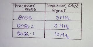
CLK-It is a clock signal. it is provides basic timing for processor operation and bus control activity clock frequency depends on the version of 8086
RESET-It is used to restart the execution. It causes the processor to immediately terminate its present activity. this signal is active high signal at must be active for at least 4 clock cycle.
READY-This is the acknowledgement from the memory or slow device that they have completed the data transfer. This signal used primary to synchronize slow peripheral with microprocessor.
TEST-The signal is used to synchronize operations of multiple processors in a system. When the WAIT instruction is being executed, the processor check this signal. if it is high the processor interrupts the execution of the program and if it is slow it continuous to execution.
RD-This signal is used for read operations it is active when low it is an output signal.
MN/MX-Dispense signal decide that what processor made operate in 8086 (minimum mode or maximum mode).
Minimum mode-the minimum mode is used for the single processor environment. Some minimum more functions are-
Maximum mode-The maximum mode is used for multi processor environment such as having a coprocessor in a system.in the maximum mode eight pins are assigned different function compared to that the minimum mode some minimum functions are-
NMI(non-maskable interrupt)-It is an an edge triggered input which browsers an interpreter quest to the microprocessor.
INTR-It is an interrupt request which is sampled during the last clock cycle of each instruction to determine if processor should enter into interrupt service routine.
CLK-It is a clock signal. it is provides basic timing for processor operation and bus control activity clock frequency depends on the version of 8086
RESET-It is used to restart the execution. It causes the processor to immediately terminate its present activity. this signal is active high signal at must be active for at least 4 clock cycle.
READY-This is the acknowledgement from the memory or slow device that they have completed the data transfer. This signal used primary to synchronize slow peripheral with microprocessor.
TEST-The signal is used to synchronize operations of multiple processors in a system. When the WAIT instruction is being executed, the processor check this signal. if it is high the processor interrupts the execution of the program and if it is slow it continuous to execution.
RD-This signal is used for read operations it is active when low it is an output signal.
MN/MX-Dispense signal decide that what processor made operate in 8086 (minimum mode or maximum mode).
Minimum mode-the minimum mode is used for the single processor environment. Some minimum more functions are-
- ALE
- INTA
- DEN'
- DT/R'
- M/IO
- WR'
- HOLD and HLDA
- ALE(address latch enable)-This signal is provided by microprocessor to the multiplex AD0-AD15 and D0-D15 using external latch. It is an active high pulse during T1 of any bus cycle.ALE signal is never faulted is always integer.
- INTA(interrupt acknowledge output)-It is an interrupt acknowledgement signal. This indicates recognition of of an interrupt request. When the microprocessor receive the signal it goes low.
- DEN(data enable)-The signal inference that trans receiver that the CPU is ready to send the received data.
- DT/R'(data transmit/receive)-This is used to decide the direction of data flow through the transreceiver full stop when the processor sends out the data the signal is high and when processor is receiving the data this signal is slow.
- M/IO'(memory / input or output)-This signal is used to distinguish between memory and I/O operation. When it is high it indicate I/O operation and when it is low it indicate memory operation.
- WR'(write)-The signal is used for write the signal. It is used write data into the memory or the output (I/O) device depending on the status of M/IO'signal.
- HOLD&HLDA- This signal is indicates that another master is requesting to take over the system was on receiving HOLD signal processor output HLDA signal high as acknowledgement full stop at the same time processor tri-state the system bus. On HOLD gives the system bus control back to the processor then output signal is low signal is on HLDA.
- QS1,QS0
- S2',S1',S0'
- LOCK'
- RQ'/GT
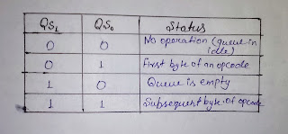
- QS1,QS0(Queue status signal)-These output signal reflect the status of the instruction queue according to the table shown below-
- S2', S1', S0'(status signal) -These three status signals indicates the type of transfer to be take place during the current bus cycle shown in figure-
- LOCK'-This signal indicates that an instruction with LOCK'prefix being executed and the bus is not to be used by another processor.
- RQ'/GT1 &RQ'/GT0(request/grant)-In the maximum mode HOLD and HLDA pins are replaced by RQ'/GT0 and RQ'/GT1 signal full stop these are the signal used by the other processes requesting the CPU to release the system bus full stop these lines are bidirectional and are used to both request and grant it a DMA operations.


Visit for movies IBOMMA
ReplyDelete